 |
M.E.T.T.S. - Consulting Engineers > White Papers > UCG-CSM Interrelationships and Synergies
UCG-CSM Interrelationships and Synergies
A submission to the Energy White Paper Secretariat, DRET Canberra, 9th May 2009
Dr. Michael C. Clarke, CPEng, FIEAust, FAusIMM, RPEQ
Consulting Engineer, Resource & Infrastructure Development
CEO, M.E.T.T.S. Pty. Ltd./Director, Pacific Power Partners LLC
Email: metts[at]]metts.com.au
Share this page:
Introduction
Underground Coal Gasification (UCG) is primarily seen as a means of producing synthesis-gas (syn-gas) from ‘stranded’ coal measures. The possible uses of the syn-gas are in the generation of electricity, the production of Fischer-Tropsch liquid fuels, methanol, dimethyl ether and other oxygenates, or ammonia and urea, and possibly its reticulation to industry as a natural gas replacement (as coal gas) or even conversion to synthetic natural gas.
Syn-gas has as active components hydrogen and carbon monoxide, and inactive components, carbon dioxide, nitrogen and water vapour. Syn-gas can also contain considerable quantities of methane, with this component being formed during syn-gas production, or simply being un-reacted (residual) coal seam methane (CSM). In using syn-gas for power generation or for the production of electricity or synthetic natural gas, the presence of residual natural gas (methane) in the feed syn-gas is welcome, for it is part of the fuel mix in power generation, or simply a fraction of the total product gas in synthetic natural gas production.
In the Fischer-Tropsch synthesis, the production of oxygenates or ammonia and urea, residual methane gas has no role and simply dilutes the active syn-gas components. The means of utilising this gas and indeed enhancing the production of this methane are examined in this article.
Underground Coal Gasification Technology
Figure 1 is a simplified UCG ‘production cell’. The syn-gas product exiting the production is a cocktail of gases, volatile and not so volatile compounds, particulates and water vapour.
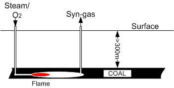
Figure 1. A UCG production cell
In its ‘raw’ state syn-gas is virtually a useless commodity, and needs an initial cleaning to be of use in power production or as a reticulated heating gas. The gas must be cooled, and the water content lowered, and tars and particulate removed. For simple uses it should be passible as a coal-gas, which in reality it is. (Note: Traditional coal-gas or town gas is the product of the destructive pyrolysis of coal in a retort with limited addition of oxidant. It traditionally was the gas used for industry and domestic applications before the advent of reticulated natural gas.)
Figure 2 is a schematic of a simplified UCG syn-gas production train. For use in syn-crude, synthetic natural gas, or fertiliser production a complex and thorough gas cleaning circuit would be required.
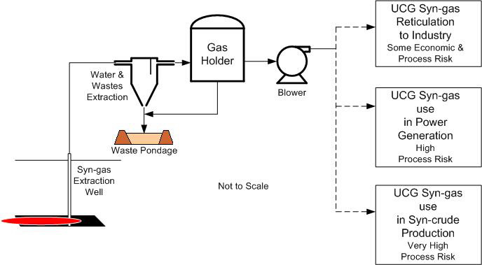
Figure 2. Syn-gas production, initial cleaning and utilisation options
Syn-Gas Quality
UCG synthesis gas varies in constituents and thus quality depending on the composition of the coal that is gasified, the oxidants used (and oxidant balance) in the gasification process, and the style of underground reactor (e.g. strip or open chamber). The syn-gas quality (as Specific Energy) for oxygen blown systems should range between 12 and 20 MJ/scm. The methane content can range from a few percent to close to 20%.
Utilising the Methane in Syn-gas
Besides direct combustion where methane will be consumed, processes such as the Fischer-Tropsch do not use the contained methane. It like nitrogen will be simply carried through the system. Two choices to gain value from the methane are to subject it to reforming or to utilise it as a component of process off-gas. These uses are demonstrated in Figures 3a and 3b.
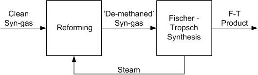
In Figure 3a, the introduction of a methane reforming step would need to be predicated by there being sufficient methane in the syn-gas to warrant such a step.
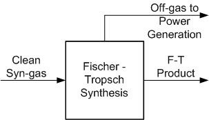
Figure 3b. The utilisation of methane (plus other residual combustible gases) in power generation
Another Scenario for Syn-Gas Methane
The technology for the separation of gases has rapidly advanced in the last quarter century, with the development of both cryogenic and membrane processes. It is now feasible to separate syn-gas from other combustible gases and thence to have that gas available for other uses.
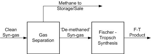
Figure 4. Methane separation from syn-gas
The Co-production of Coal Seam Methane with UCG
The process of UCG cannot truly be separated from Coal Seam Methane (CSM) production. CSM, if present in the coal, will be liberated during the development of the UCG cells, during the operation of the cells and post closure of the cell. During the operation of the cell some will be converted (reformed) to hydrogen and carbon monoxide, some will be reacted to form more exotic compounds, and some will be combusted to water and carbon monoxide.
Post cell operation (after extinguishing the combustion zone) CSM will continue to be released. This release will be enhanced through crushing, collapse and subsidence involved with the cell cavity, and through floor heave into the cavity. Gas contained in strata above and below the cavity will be released into cracks caused by the ground movement. In reality the production of CSM in the zone around a UCG cavity will be similar to CSM produced in mining goaf areas and where the UCG cavity system is extensive will be analogous to gas production in a long-wall goaf.
The Influence and Management of the Groundwater Hydrostatic Head
In Figure 5, the movement of gas and water towards the UCG cavity are indicated. In a UCG system the groundwater hydrostatic head has a major role in containing the UCG gases and liquids, and in practice the hydrostatic pressure PH is greater that the gas pressure in the cavity PC. The effect of keeping PH > PC is to prevent loss of the product gas and contain pollutants. If the pressure differential is maintained post combustion extinguishing, CSM will continue to flow into the cavity.
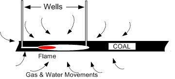
Figure 5. The flow of gas and water into the UCG cavity
Enhancing CSM Recovery with UCG
UCG systems are being developed that mimic short-wall mining. Panels of hundreds of metres width and up to a kilometre in length will be delineated in the coal resource, and strips (faces) of say 60m and greater will be delineated in the panels. UCG will proceed in a retreating fashion in one or more faces. Syn-gas will be produced in these faces, which will be divided by substantial barriers. The fire front as well as retreating will tend to take the upper parts of the seam, and gas will rise in the cavity whilst fluids will flow to the lower parts of the cavity.
Over time the barriers between faces will crush, the floor of the cavities will crack and heave, whilst the roof will crack and collapse. The void will fill with broken material with pore spaces filling with water and residual UCG fluids. Where the void is inundated with water and this water is at the strata’s hydrostatic pressure, CSM movement into the void will be stopped. If the void can be maintained at less than the hydrostatic head, then gas will still move towards the void.
In planning a UCG panel, consideration should be extended CSM extraction. The design and management of the developing cavities to provide for a continuing flow of gas to an extraction point is a necessary measure. The removal of water from the cavities may also be required, at least as a temporary measure.
The Environment and UCG/CSM
The extraction of CSM is usually accomplished with considerable water co-extraction, water that is often saline and thus presents environmental challenges. UCG promoters promise to keep most of its pollutants contained in the formed cavities. If UCG liquors need to extracted to lower the pressure in the cavities to assist gas flow, then these liquors will need to be handled in an environmentally responsible way.
In Figure 2, there is shown an impoundment for wastes extracted during syn-gas cleaning. This impoundment could be expanded to take contaminated waters from UGC cavity dewatering. Evaporation could be used to reduce volume, with the final wastes being pumped into the cavities for secure disposal once CSM extraction was complete.
Where, When and Why: Methane Production from/with UGC Operations
The quantity of methane contained in a cubic metre of coal varies greatly and can be from trace quantities to say 25m3/tonne. The challenge for recovering this gas has often been the low permeability of the strata, in that gas does not easily flow through the coal and associated strata. New horizontal drilling techniques have greatly improved access to gas, but the techniques are still essentially two-dimensional. The use of UCG technology creates the opportunity to ‘open’ tight gas holding strata on a three-dimensional basis.
Where CSM is found in seams and strata above and below the seam to be exploited (Figure 6) movements associated with the UCG cavity will increase permeability thus releasing gas. Given the physical changes to strata and the time delay that will occur from operating multiple UCG faces, great opportunities for gas release will be created.
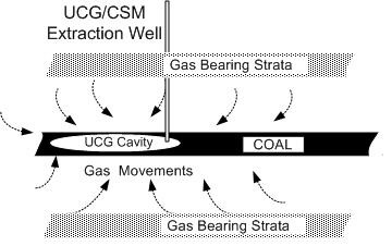
Figure 6a. The use of an UCG cavity for enhancing CSM recovery
Post UCG extraction could be through the original UCG extraction wells or through additional CSM wells that take advantage of the strata ‘breaking’ that was facilitated by UCG extraction.
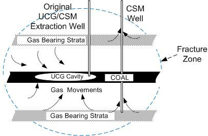
Figure 6b. The use of an UCG cavity for enhancing CSM recovery with CSM extraction well and fracture zone
Where a series of UCG burns have been undertaken in parallel, as envisioned in the CSIRO/ Carbon-Energy Knife-edge CRIP (Controlled Retracting Injection Point) Technology (Under Development), a multiple series of parallel burn zones can be envisaged, separated by barriers, but creating a vast fracture zone. In the case of deep and tight (low permeability) gas bearing strata, this fracture system will allow for the movement of gas in vertical (perpendicular to seam) as well as in in-seam directions.
The extraction of ‘associated’ methane during and post UCG operations add dimensions to resource recovery in terms of the useful Joules that can be extracted and the extension of time over which a total CSM/coal resource can be ‘mined’. It also allows the UCG operator to take advantage of installed borehole and waste management infrastructure and it provides the UCG operator with a cash-flow independent of the return from syn-gas products.
UCG with natural gas extraction can be a truly win-win situation.
Challenges to UCG Syn-gas Production and CSM Co-extraction
UCG in combination with the enhanced extraction of CSM have the potential of:
• ‘meeting our domestic energy requirements cost-effectively and securely while meeting environmental objectives’, and addressing
• cleaner energy supporting environmental objectives,
• adequate (and secure) energy sufficient to support economic and social activity,
• reliable energy supply with minimal disruptions, and
• affordable energy supplied at a price that does not reduce the competitiveness of the economy and supports continued investment in the energy sector’.
They also have the potential to facilitate additional ‘exports of competitively marketed energy resources’.
To achieve the above we should look to undertaking the following:
1. Legislative bottlenecks with regard to mining and petroleum licences will need to be resolved. The definition of UCG being mining and CSM extraction being petroleum needs to be reviewed. The origin of gas in strata associated with coal may not always be clear-cut, and an extraction licence that includes coal and regional gas should be created.
2. The need for continuing pressure management in UCG cavities and possibly contaminated water management are other challenges. Good engineering of specific UCG operations should be able to overcome those challenges.
3. A significant challenge will be to find the situation where UCG Syn-gas Production and CSM Co-extraction can best be demonstrated. Gaining a good understanding of the nominated resource, the technologies required and their synergies, the modelling of the total process, producing a budgeted project plan, and finding the finances are all required to make the concept a reality.
NOTE:
You are welcome to quote up to a maximum of three paragraphs from the above white paper, on condition that you include attribution to this website, as follows:
SOURCE: M.E.T.T.S. Pty. Ltd. Website http://www.metts.com.au
Share this page:
Author: Michael C Clarke
(Michael C Clarke on Google+)
Introduction
Underground Coal Gasification (UCG) is primarily seen as a means of producing synthesis-gas (syn-gas) from ‘stranded’ coal measures. The possible uses of the syn-gas are in the generation of electricity, the production of Fischer-Tropsch liquid fuels, methanol, dimethyl ether and other oxygenates, or ammonia and urea, and possibly its reticulation to industry as a natural gas replacement (as coal gas) or even conversion to synthetic natural gas.
Syn-gas has as active components hydrogen and carbon monoxide, and inactive components, carbon dioxide, nitrogen and water vapour. Syn-gas can also contain considerable quantities of methane, with this component being formed during syn-gas production, or simply being un-reacted (residual) coal seam methane (CSM). In using syn-gas for power generation or for the production of electricity or synthetic natural gas, the presence of residual natural gas (methane) in the feed syn-gas is welcome, for it is part of the fuel mix in power generation, or simply a fraction of the total product gas in synthetic natural gas production.
In the Fischer-Tropsch synthesis, the production of oxygenates or ammonia and urea, residual methane gas has no role and simply dilutes the active syn-gas components. The means of utilising this gas and indeed enhancing the production of this methane are examined in this article.
Underground Coal Gasification Technology
Figure 1 is a simplified UCG ‘production cell’. The syn-gas product exiting the production is a cocktail of gases, volatile and not so volatile compounds, particulates and water vapour.
Figure 1. A UCG production cell
In its ‘raw’ state syn-gas is virtually a useless commodity, and needs an initial cleaning to be of use in power production or as a reticulated heating gas. The gas must be cooled, and the water content lowered, and tars and particulate removed. For simple uses it should be passible as a coal-gas, which in reality it is. (Note: Traditional coal-gas or town gas is the product of the destructive pyrolysis of coal in a retort with limited addition of oxidant. It traditionally was the gas used for industry and domestic applications before the advent of reticulated natural gas.)
Figure 2 is a schematic of a simplified UCG syn-gas production train. For use in syn-crude, synthetic natural gas, or fertiliser production a complex and thorough gas cleaning circuit would be required.
Figure 2. Syn-gas production, initial cleaning and utilisation options
Syn-Gas Quality
UCG synthesis gas varies in constituents and thus quality depending on the composition of the coal that is gasified, the oxidants used (and oxidant balance) in the gasification process, and the style of underground reactor (e.g. strip or open chamber). The syn-gas quality (as Specific Energy) for oxygen blown systems should range between 12 and 20 MJ/scm. The methane content can range from a few percent to close to 20%.
Utilising the Methane in Syn-gas
Besides direct combustion where methane will be consumed, processes such as the Fischer-Tropsch do not use the contained methane. It like nitrogen will be simply carried through the system. Two choices to gain value from the methane are to subject it to reforming or to utilise it as a component of process off-gas. These uses are demonstrated in Figures 3a and 3b.
In Figure 3a, the introduction of a methane reforming step would need to be predicated by there being sufficient methane in the syn-gas to warrant such a step.
Figure 3b. The utilisation of methane (plus other residual combustible gases) in power generation
Another Scenario for Syn-Gas Methane
The technology for the separation of gases has rapidly advanced in the last quarter century, with the development of both cryogenic and membrane processes. It is now feasible to separate syn-gas from other combustible gases and thence to have that gas available for other uses.
Figure 4. Methane separation from syn-gas
The Co-production of Coal Seam Methane with UCG
The process of UCG cannot truly be separated from Coal Seam Methane (CSM) production. CSM, if present in the coal, will be liberated during the development of the UCG cells, during the operation of the cells and post closure of the cell. During the operation of the cell some will be converted (reformed) to hydrogen and carbon monoxide, some will be reacted to form more exotic compounds, and some will be combusted to water and carbon monoxide.
Post cell operation (after extinguishing the combustion zone) CSM will continue to be released. This release will be enhanced through crushing, collapse and subsidence involved with the cell cavity, and through floor heave into the cavity. Gas contained in strata above and below the cavity will be released into cracks caused by the ground movement. In reality the production of CSM in the zone around a UCG cavity will be similar to CSM produced in mining goaf areas and where the UCG cavity system is extensive will be analogous to gas production in a long-wall goaf.
The Influence and Management of the Groundwater Hydrostatic Head
In Figure 5, the movement of gas and water towards the UCG cavity are indicated. In a UCG system the groundwater hydrostatic head has a major role in containing the UCG gases and liquids, and in practice the hydrostatic pressure PH is greater that the gas pressure in the cavity PC. The effect of keeping PH > PC is to prevent loss of the product gas and contain pollutants. If the pressure differential is maintained post combustion extinguishing, CSM will continue to flow into the cavity.
Figure 5. The flow of gas and water into the UCG cavity
Enhancing CSM Recovery with UCG
UCG systems are being developed that mimic short-wall mining. Panels of hundreds of metres width and up to a kilometre in length will be delineated in the coal resource, and strips (faces) of say 60m and greater will be delineated in the panels. UCG will proceed in a retreating fashion in one or more faces. Syn-gas will be produced in these faces, which will be divided by substantial barriers. The fire front as well as retreating will tend to take the upper parts of the seam, and gas will rise in the cavity whilst fluids will flow to the lower parts of the cavity.
Over time the barriers between faces will crush, the floor of the cavities will crack and heave, whilst the roof will crack and collapse. The void will fill with broken material with pore spaces filling with water and residual UCG fluids. Where the void is inundated with water and this water is at the strata’s hydrostatic pressure, CSM movement into the void will be stopped. If the void can be maintained at less than the hydrostatic head, then gas will still move towards the void.
In planning a UCG panel, consideration should be extended CSM extraction. The design and management of the developing cavities to provide for a continuing flow of gas to an extraction point is a necessary measure. The removal of water from the cavities may also be required, at least as a temporary measure.
The Environment and UCG/CSM
The extraction of CSM is usually accomplished with considerable water co-extraction, water that is often saline and thus presents environmental challenges. UCG promoters promise to keep most of its pollutants contained in the formed cavities. If UCG liquors need to extracted to lower the pressure in the cavities to assist gas flow, then these liquors will need to be handled in an environmentally responsible way.
In Figure 2, there is shown an impoundment for wastes extracted during syn-gas cleaning. This impoundment could be expanded to take contaminated waters from UGC cavity dewatering. Evaporation could be used to reduce volume, with the final wastes being pumped into the cavities for secure disposal once CSM extraction was complete.
Where, When and Why: Methane Production from/with UGC Operations
The quantity of methane contained in a cubic metre of coal varies greatly and can be from trace quantities to say 25m3/tonne. The challenge for recovering this gas has often been the low permeability of the strata, in that gas does not easily flow through the coal and associated strata. New horizontal drilling techniques have greatly improved access to gas, but the techniques are still essentially two-dimensional. The use of UCG technology creates the opportunity to ‘open’ tight gas holding strata on a three-dimensional basis.
Where CSM is found in seams and strata above and below the seam to be exploited (Figure 6) movements associated with the UCG cavity will increase permeability thus releasing gas. Given the physical changes to strata and the time delay that will occur from operating multiple UCG faces, great opportunities for gas release will be created.
Figure 6a. The use of an UCG cavity for enhancing CSM recovery
Post UCG extraction could be through the original UCG extraction wells or through additional CSM wells that take advantage of the strata ‘breaking’ that was facilitated by UCG extraction.
Figure 6b. The use of an UCG cavity for enhancing CSM recovery with CSM extraction well and fracture zone
Where a series of UCG burns have been undertaken in parallel, as envisioned in the CSIRO/ Carbon-Energy Knife-edge CRIP (Controlled Retracting Injection Point) Technology (Under Development), a multiple series of parallel burn zones can be envisaged, separated by barriers, but creating a vast fracture zone. In the case of deep and tight (low permeability) gas bearing strata, this fracture system will allow for the movement of gas in vertical (perpendicular to seam) as well as in in-seam directions.
The extraction of ‘associated’ methane during and post UCG operations add dimensions to resource recovery in terms of the useful Joules that can be extracted and the extension of time over which a total CSM/coal resource can be ‘mined’. It also allows the UCG operator to take advantage of installed borehole and waste management infrastructure and it provides the UCG operator with a cash-flow independent of the return from syn-gas products.
UCG with natural gas extraction can be a truly win-win situation.
Challenges to UCG Syn-gas Production and CSM Co-extraction
UCG in combination with the enhanced extraction of CSM have the potential of:
• ‘meeting our domestic energy requirements cost-effectively and securely while meeting environmental objectives’, and addressing
• cleaner energy supporting environmental objectives,
• adequate (and secure) energy sufficient to support economic and social activity,
• reliable energy supply with minimal disruptions, and
• affordable energy supplied at a price that does not reduce the competitiveness of the economy and supports continued investment in the energy sector’.
They also have the potential to facilitate additional ‘exports of competitively marketed energy resources’.
To achieve the above we should look to undertaking the following:
1. Legislative bottlenecks with regard to mining and petroleum licences will need to be resolved. The definition of UCG being mining and CSM extraction being petroleum needs to be reviewed. The origin of gas in strata associated with coal may not always be clear-cut, and an extraction licence that includes coal and regional gas should be created.
2. The need for continuing pressure management in UCG cavities and possibly contaminated water management are other challenges. Good engineering of specific UCG operations should be able to overcome those challenges.
3. A significant challenge will be to find the situation where UCG Syn-gas Production and CSM Co-extraction can best be demonstrated. Gaining a good understanding of the nominated resource, the technologies required and their synergies, the modelling of the total process, producing a budgeted project plan, and finding the finances are all required to make the concept a reality.
NOTE:
You are welcome to quote up to a maximum of three paragraphs from the above white paper, on condition that you include attribution to this website, as follows:
SOURCE: M.E.T.T.S. Pty. Ltd. Website http://www.metts.com.au
Share this page:
Author: Michael C Clarke
(Michael C Clarke on Google+)
M.E.T.T.S. Pty. Ltd. - Consulting Engineers PO Box 843, Helensvale QLD 4212, Australia TEL: (07) 5502 8093 • (Int'l) +61-7-5502 8093 EMAIL: metts[at]metts.com.au Copyright • Privacy • Terms of Use © 1999-2014 M.E.T.T.S. Pty. Ltd. All Rights Reserved. |
.