M.E.T.T.S. - Consulting Engineers > White Papers > Coming to Grips with Carbon Capture and Storage
Coming to Grips with Carbon Capture and Storage
Is it possible to produce a roadmap for major carbon dioxide producers and emitters to achieve efficient and economically viable carbon capture and storage (CCS)?
Dr. Michael C. Clarke*, CPEng, FIEAust, FAusIMM, RPEQ
CEO, M.E.T.T.S. Pty. Ltd.
Consulting Engineers, Resource Management and Infrastructure Development
Gold Coast, QLD, Australia
Email: metts[at]metts.com.au
Originally published in: Energy Generation, January-March 2011.
Share this page:
The question above is increasingly being faced by power generators, oil refinery operators, LNG producers, cement plant operators and iron and steel producers, all of which have large carbon footprints, and all of which will need to consider reducing their liability to pay carbon taxes when (if?) they are introduced.
Any roadmap will need to incorporate the three key elements that are required to make CCS a reality, with these elements being:
• carbon capture systems for power generation or other carbon producing activities
• carbon transport systems suitable to the scale of the demonstration project
• carbon sequestration (storage) opportunities to complement capture and transport.
Each of the elements are interdependent, but may be ranked in accordance with their overall importance, with the existence of carbon sequestration opportunities being ahead of carbon capture systems and carbon transport systems respectively.
A serious note: If there are no sequestration opportunities then it would be unwise to waste time looking at carbon capture opportunities and carbon transport systems.
Major sources of carbon dioxide emissions
Three specific sources of carbon dioxide emissions are considered that are of relevance to major raw energy producers. These are power generation using coal, power generation using natural gas and liquefied natural gas (LNG) production.
Power generation using black coal is a major source of carbon dioxide, with emission intensities ranging from 650–850 kg CO2-e/MWh depending on the conversion technology employed. For lignite the emission intensities are high, and can be over one tonne CO2-e/MWh. The concentration is typically around 14% in the flue gas of traditional pulverised fuel power stations. A concentration of 14% CO2 is technically viable for capture post combustion.
Power generation using natural gas is another and increasingly significant source of carbon dioxide emissions. The emission intensities from open cycle (often peaking plant) are around 650 kg CO2-e / MWh, and from base load combined cycle around 450 kg CO2-e/MWh. The concentration of CO2 is typically only around 4–6% in the flue gas of natural gas power stations. A concentration of 4% CO2 is technically and definitely not economically viable for post combustion capture, since the plant required for capture is proportional to the flue gas flow which is relatively very high.
LNG production plus logistics accounts for around 15% of input raw gas fed into a LNG plant. That gas is used in the raw gas purification and liquefaction (see Figure 1), thence transport and eventual re-gasification at the point of use. Another source of CO2 in LNG production is the CO2 contained in raw gas extracted from wells. Here, CO2 concentrations range from a trace to over 40%, with the Western Australian Gorgon group reporting 14% in their raw gas feed.

Figure 1 – LNG general schema
The requirement for LNG is that it should have less than 50 parts per million CO2 (by volume) to avoid the formation of icy solids, as well as no more than trace sulphur. Also there are variations in the energy content of LNG in accordance with the amount of residual ethane and heavier fractions that are left in the liquefied product (Figure 2).
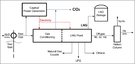
Figure 2 – LNG production process (inputs and outputs)
An LNG train with energy inputs and product outputs is shown above. In this situation raw natural gas with sufficient ‘wet’ components (for recovery) – those being ethane, LPG and Natural Gas Liquids (NGLs) plus a recoverable helium content – is used as a feed to an LNG plant. The CO2 content of the flue gas is made up of a component from power generation and a component from CO2 stripping from the raw gas.
If the CO2 content is greater than 10% in the flue gas, then the technology and economics of post CO2 stripping are relatively favourable. If the flue gas contains over 20% CO2, then recovery is even more technically and economically viable.
Note: Having a clean and concentrated source of CO2 is one secret of successful carbon capture with acceptable economics.
Capturing carbon dioxide in coal-fired power generation
One of the most ‘obvious’ sources of carbon dioxide is coal-fired power generation. This activity is a ‘cause bellicose’ to those supporting green and renewable energy. Concepts of reducing and possibly eliminating carbon dioxide emissions from power generation have been put forward, with these concepts including carbon capture leading to sequestration (permanent storage).
Three carbon capture technologies are in different stages of development for application to the coal-fired power industry. The first and most mature technology (Figure 3) is post-combustion capture using amines or ammonia.
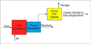
Figure 3 – Post-combustion capture process
The above capture system morphs into the following schema (Figure 4) which includes inputs and outputs of materials and energy.
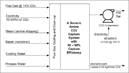
Figure 4 – Post-combustion capture (inputs and outputs)
The second option for carbon capture involves firing coal with oxygen that is diluted with flue gas. This scheme‘s general process diagram is shown in Figure 5.
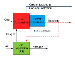
Figure 5 – Oxy-firing process
The last option is pre-combustion capture, where the only gas to be combusted is hydrogen, and produces water vapour (Figure 6).
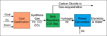
Figure 6 – Pre-combustion capture process
Question: Can any of these capture systems be developed to a scale that can match the carbon output of a modern base-load coal-fired power station of say >500 MWe gross output?
Carbon Transport – an activity with major ‘social license’ implications, as well as technical challenges
CO2 is one of the most traded and thus transported gases in the world. Beverage production, fire control, food processing and enhanced oil recovery all use the gas. The volumes of CO2 gas that are being considered for sequestration will however dwarf the present uses of the gas, and thus its transport in great volume will create major challenges for the technology and for society. The societal challenge will be convincing communities that CO2 transport, by pipeline or tanker, is safe and desirable.
A technical and economic challenge for CO2 transport is that the source of CO2 should be in relatively close proximity to the intended storage site. Industry wisdom presently holds that the distances should be no more than 100–200 km to avoid multiple pipeline compressor stations or excessive road/rail/barge transport costs and carbon footprints.
Storage – the multi-billion dollar question
Geological storage is generally considered the most promising storage technique for CO2 and it should be noted that Australia has been supporting the development of geological storage systems through the Commonwealth-funded Global Carbon Capture and Storage Institute (GCCSI) in Canberra.
The general principle of the technology is that a purified stream of CO2 is directed into secure and extensive geological storage structures, some of which are described in Figure 7.
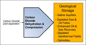
Figure 7 – Geological storage general options
Questions of storage security, that being permanent and ‘leak-proof’, and indeed finding storage sites that are extensive enough for major CCS projects and have the appropriate logistics to the CO2 source must be addressed.
Of the options for storage shown in Figure 7, the use of capture for enhanced oil recovery can offer a direct financial benefit from a storage activity. One such example is the North Dakota to Saskatchewan CO2 pipeline that delivers CO2 from a synthetic natural gas plant to a depleting oilfield, where oil recovery has been enhanced. Other options for storage probably have little or no financial return likelihood except for earning carbon credits and avoiding carbon taxes.
Other carbon sinks that have been put forward are ‘green’ options, and include reafforestation projects where carbon is captured in forest growth over defined periods, before sequestration into timber that has long lifetime uses, and algal capture systems where algae would be used for the production of liquid transport fuels, thus displacing the use of traditional oil-based fuels. Such ‘green’ sinks however have not been fully considered for creating carbon credits, partially due to the challenges associated with measurement and verification of carbon uptake and destiny.
Developing roadmaps and templates for CCS activities
Figure 8 shows the inputs required for a CCS activity. The three major lobes –capture, transport and storage, lobes A, B and C – are essentially technical concerns and must be supported by inputs that are not technical, but which influence the viability of CCS projects and have the potential to be project stoppers.
Those required inputs are: competent financial/economic structures and analyses, a strong regulatory regime and the creation of a social licence to plan, construct, commission and most importantly to operate the CCS activity.
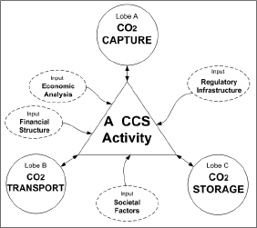
Figure 8. Inputs into a CCS activity
Lobe by lobe, some specific factors to be considered
Lobe A – The primary requirement is the identification of a suitable source of carbon. This lobe also needs a good understanding of the science and engineering of CC systems. The hazards associated with carbon capture must be understood and mitigated.
Lobe B – Carbon transport will be a site-specific activity, with transport options being devised with reference to local transport regulations, societal expectations and perceptions, and transport economics.
Lobe C – Geological storage requires the presence of suitable carbon sinks. The sinks should match the expected carbon capture characteristics (quantities and flow patterns). A good understanding of engineering required for safe storage and geological hazards will be required.
Threats and weaknesses (the possible show stoppers)
Lack of understanding and thus support for CCS, legislative and regulatory hurdles, perceptions of hazards, the inability to find suitable opportunities and partnerships, the lack of project transparency, and uncertainty regarding carbon pricing are all possible show stoppers that must be considered by CCS project proponents.
Decision trees (roadmaps for major CCS projects)
A series of decision trees could be developed for assisting CCS project proponents. One tree is an initial project test tool for roadmaps for major CCS projects (Figure 9).
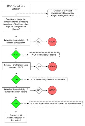
Figure 9 – Decision Tree for CCS project
Penalties and costs of introducing CCS in coal-fired power generation
Capturing CO2 requires considerable energy. In a ‘generic’ power generation plant such as that shown in Figure 10, there is a significant loss of conversion efficiency, and indeed a significant portion of the CO2 produced comes from the CCS operation.
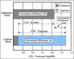
Figure 10 – Emissions with and without CCS for generic power station
For a nominal 500 MWe BAU ‘generic’ power station, the output to the grid would be reduced by around 110 MWe if a post-capture CCS system was retrofitted to the plant (Figure 11).
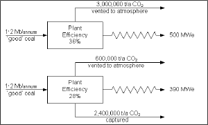
Figure 11 – Power station output with and without CCS
Conclusion
CCS is technically possible for existing and future coal-fired power plants provided they are in reasonable proximity to suitable carbon sinks. Efficiency losses will occur with CCS plants over BAU plants, with the MWh presented to the grid being reduced by 20–30% per unit of coal consumed. The cost of electricity will be greater for CCS plants, due to both efficiency losses and extra capital expenditure. That additional cost could range from 40–80% of BAU wholesale power cost.
A final word
Technologies for carbon capture and storage for carbon emissions are being developed for power generation, natural gas processing and other carbon-intensive industries. For coal-fired power generation, having new, planned power stations being ‘carbon capture ready’ is becoming a necessity.
CCS will however not be cheap to install and manage, and with power generation from fossil fuels will result in significantly increased power prices. Its acceptance by society will require a great deal of unambiguous and factual explanation of the reasons for its deployment, and careful weighing-up of green alternatives that are being proposed for power generation in our society.
* Dr Mike Clarke is the CEO of M.E.T.T.S. Pty Ltd, and is currently the Power Generation Expert on the Asian Developments Bank’s project TA 7575: Determining the Potential for Carbon Capture and Storage for South East Asia, 2010–2011.
NOTE:
You are welcome to quote up to a maximum of three paragraphs from the above white paper, on condition that you include attribution to this website, as follows:
SOURCE: M.E.T.T.S. Pty. Ltd. Website http://www.metts.com.au
Share this page:
Author: Michael C Clarke
(Michael C Clarke on Google+)
M.E.T.T.S. Pty. Ltd. - Consulting Engineers PO Box 843, Helensvale QLD 4212, Australia TEL: (07) 5502 8093 • (Int'l) +61-7-5502 8093 EMAIL: metts[at]metts.com.au Copyright • Privacy • Terms of Use © 1999-2014 M.E.T.T.S. Pty. Ltd. All Rights Reserved. |
.

